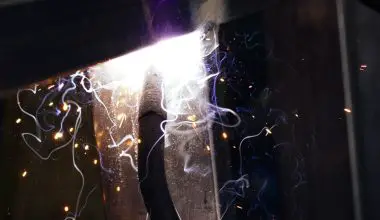
The arcs should begin to flutter. The reason this is happening is that the arcs is acting as a rectifier, which means it is converting the alternating current of the power supply into a direct current, or DC.
This is a very important concept to understand, because it will help you understand why the AC/DC converter is so important to your system.
If you don’t understand this concept, you will not be able to properly design your power system, and you may end up with a system that doesn’t work as well as you would like it to.
Table of Contents
What is rectifier machine?
A rectifier is an electrical device that converts alternating current (AC), which periodically reverses direction, to direct current (DC), which flows in only one direction. The transformer converts AC to DC in the reverse operation. A transformer is made up of two parts: a primary winding and a secondary winding. Each winding has a positive and negative terminal.
When the primary is energized, the positive terminal of the winding is connected to the ground, and vice versa when the secondary is turned on. A transformer’s primary and secondary are connected in series, so that the voltage across the two terminals is the same. In this way, a transformer can be used to convert AC power into DC power.
What is purpose of a rectifier in a welding sets electrical circuit?
In electric welding, bridge rectifier circuits are used to provide steady and reliable power to the welding machine. They are also used in many other applications, such as in the manufacture of high-voltage transformers. In this article, we will look at some of the uses of this type of circuit, as well as how it can be used. Rectifier circuit for welding In electrical engineering, the term “rectifier” refers to a device that converts electrical energy into mechanical energy.
This is done by passing a current through a resistor, which in turn converts the current into a voltage. The voltage is then passed through an inductor to produce a magnetic field. When this field is applied to an object, it causes the object to vibrate, causing it to move. For example, if you hold a piece of metal in your hand, you will feel a vibration as the metal vibrates.
If you apply an electric current to this metal, this current will cause the vibration to be amplified, producing a sound that you can hear as you move your finger across the surface. A similar effect is produced when you press a button on a computer keyboard.
How does a rectifier work?
A rectifier is a device that converts an oscillating two-directional alternating current (AC) into a single-directional direct current (DC). A wide variety of physical forms can be taken by rectifiers.
Rectifiers are used to convert AC into DC, but they can also be used for other purposes, such as converting DC to AC or AC to DC-DC converters. In this article, we’ll look at some of the different types of rectifiers and how they work.
What is rectifier with diagram?
A device or a circuit which rectifies both halves of each cycle of an alternating voltage is called a full-wave rectifier. The alternating voltage is applied across the primary coil of a transformer with a center-tapped secondary. The secondary coil is connected to the secondary winding of the transformer, and the two coils are connected in series.
An electric circuit consists of two or more conductors, each of which has a potential difference between it and any other conductor. The voltage across a conductor is the product of its resistance (R) and its capacitance (C). A voltage-coupled device (VCD) is a device that can be used to rectify a voltage.
VCDs are used in many applications, but they are particularly well suited for the rectification of alternating current (AC) voltages. An alternating-voltage-to-current converter (AVC) converts an AC voltage into a DC voltage, which is then converted back into AC by a current-limiting resistor.
Can you test a welder with a multimeter?
An additional test for ‘ARC Welders’ is to make sure that the mains voltage does not show up at the output terminals. This can be done by using a multimeter to measure the voltage across the ground terminals.
If this test is negative, then the ‘Arc Welder’ will not be able to weld. If it is positive, it means that the arc welder is working properly. This test can also be used to check if the welders are connected correctly.
What does a transformer do in a welder?
The transformer, housed in a welding machine, is used to convert the high-voltage input or, primary power, from the wall plug into a low alternating current input. The transformer is then connected to the AC input of the inverter, which converts the DC input to AC. AC output is fed to a rectifier, a device that converts AC to DC and then back again.
This is called a DC-to-AC converter (DAC), and it is the most common type of AC converter in use today. It is also known as a dc-dc converter, or DC to dc converter. In the case of a DAC, the output voltage is divided by the input voltage, and the result is converted to an AC voltage.
You would then use this voltage to drive a 5 volt DC power supply. If you wanted to use the 5 volts DC output to power a lightbulb, then the voltage would need to be multiplied by a factor of 5, so that it would be 5/240 = 1.
What are the 3 main part of rectifier circuit?
The transformer, stack, and cabinet make up a rectifier. The transformer’s purpose is to separate the incoming AC voltage from the secondary side, which is adjusted to control the output voltage. The stack is the most important component in the circuit, as it controls the amount of current flowing through the coil.
It is made up of a series of resistors and capacitors that are connected in series to form a capacitor-to-resistor (C/R) circuit. This allows the current to flow in one direction, but not the other. For example, if the voltage on the primary side is 5 volts, the stack will have a value of 1.5 volts.
In this case, it is not necessary to add a resistor to the input of this circuit to prevent over-voltage. Instead, you can simply connect a 1-ohm resistor across the capacitor and the resistor will act as a voltage divider between the two sides. You can also use a single-ended load, such as an audio amplifier, to create a similar effect.
Why filter is used in rectifier?
A filter circuit is used to eliminate the ripples in the amplifier’s output voltage. The output of an amplifier is connected to the input of a voltage divider. The input voltage is applied to a resistor R1 and a capacitor C1. When the capacitor is fully charged, the voltage across the resistor is reduced to zero. This reduces the amount of current flowing through the circuit.
Which type of rectifier is mostly used and why?
This report will show you how to make and work a bridge rectifier. The most popular method for full-wave rectification is the simple bridge rectifier circuit. The basic idea is to use a capacitor in series with a resistor in parallel. The capacitor is connected to the output of the amplifier and the resistor to ground. When the voltage across the capacitor reaches a certain value, it causes a current to flow between the two resistors.
This current is then converted into a voltage that can be used to drive a transistor or other device. In this case, the transistor is an op-amp, which is a device that converts an electrical signal into an electronic signal. Op-amps are used in a wide variety of electronic devices, such as amplifiers, transistors, diodes, capacitors, and so on. They are also known as “gate-channel” devices because they convert electrical signals into electronic signals.
Gate-channels are very common in digital circuits, but they can also be found in other types of circuits as well. For example, a diode can convert an AC voltage to a DC voltage. A capacitor, on the other hand, can only convert AC to DC, not DC to AC.